I2C Extender
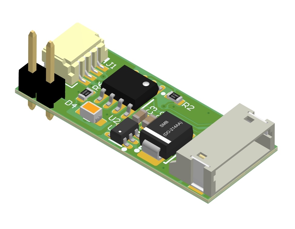
I2C extender improves signal/noise ratio, allows using long I2C cable, and improves the reliability of I2C communication in a harsh environment.
Features
- An optional power supply input (+VCC) to increase the working voltage of the buffered line (up to 14V); if not connected, I2C Extender uses a +5V power line.
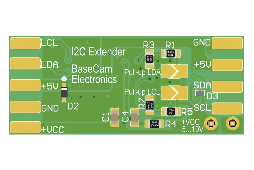
- Option to select pull-up resistance by jumpers, depending on the number of connected devices on the buffered line and the voltage of the power supply.
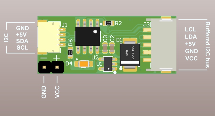
- Two connection options: plug & socket connector or solder pads on the bottom side.
- I2C line connector is compatible with the SBGC32 I2C IMU cable
- +VCC and +5V are passed transparently to all devices via a 5-pin connector
How to use
Each device on a regular I2C line is connected to the I2C inputs SDA, SCL of the I2C Extender board (one extender per device). LDA, LCL outputs of all extenders are connected together by a long "buffered" line.
Connection diagram example
WARNING: Do not connect regular I2C devices (having 3.3V logic levels and low current capabilities) to the buffered line! There is a risk of damage!
Configuring pull-up resistance for buffered line
The following table provides jumper configurations to select the optimal (minimal allowed) pullup resistance according to the number of devices and the VCC voltage level. The table provides configuration for a single line (LDA or LCL), another line has the same configuration.
| Number of devices | Jumpers soldered | Resistance, Ohm |
| VCC=5V, 170 Ohm. min. | ||
| 5 | 2 | 183 |
| 4 | 2 | 202 |
| 3 | 3 | 169 |
| 2 | 2 | 200 |
| VCC=10V, 380 Ohm. min. | ||
| 5 | 0 | 400 |
| 4 | 0 | 500 |
| 3 | 0 | 666 |
| 2 | 1 | 404 |
Specifications
| Dimensions | 11.5mm x 27.5mm |
| Weight | 1.78 g |
| Power supply voltage range on VCC pin |
4.5V ... 14V |
| Continuous output current on buffered line (LCL, LDA pins) | max. 60 mA |
| Bus capacitance | max. 3000pF |
Downloads
Support
Type your question or comment below. Answer will be sent at your E-mail within 24 hours on workdays.


