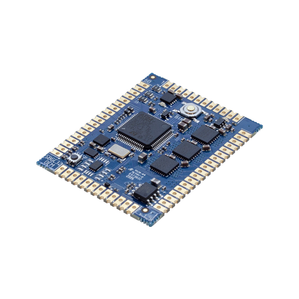
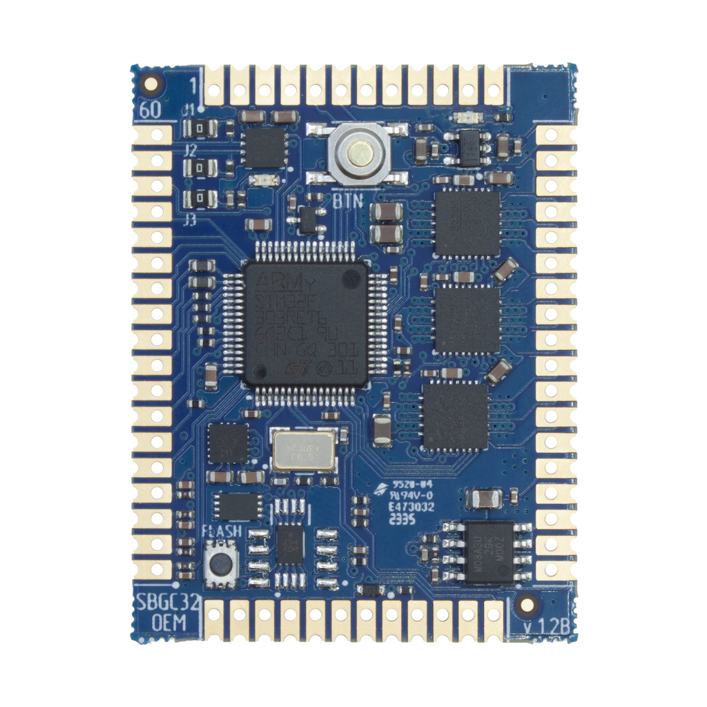
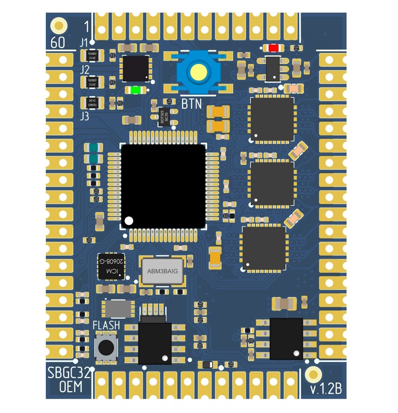
BaseCam SimpleBGC 32-bit OEM v1.2
This is a compact but powerful and function-rich gimbal controller, suitable for small-, medium- and even large-sized gimbals. The main difference from other our controllers — it's designed to be built in into a customer's host controller or motherboard rather than used stand-alone.
Features
- Built-in powerful (for their size) motor drivers with possibility to use external motor drivers*
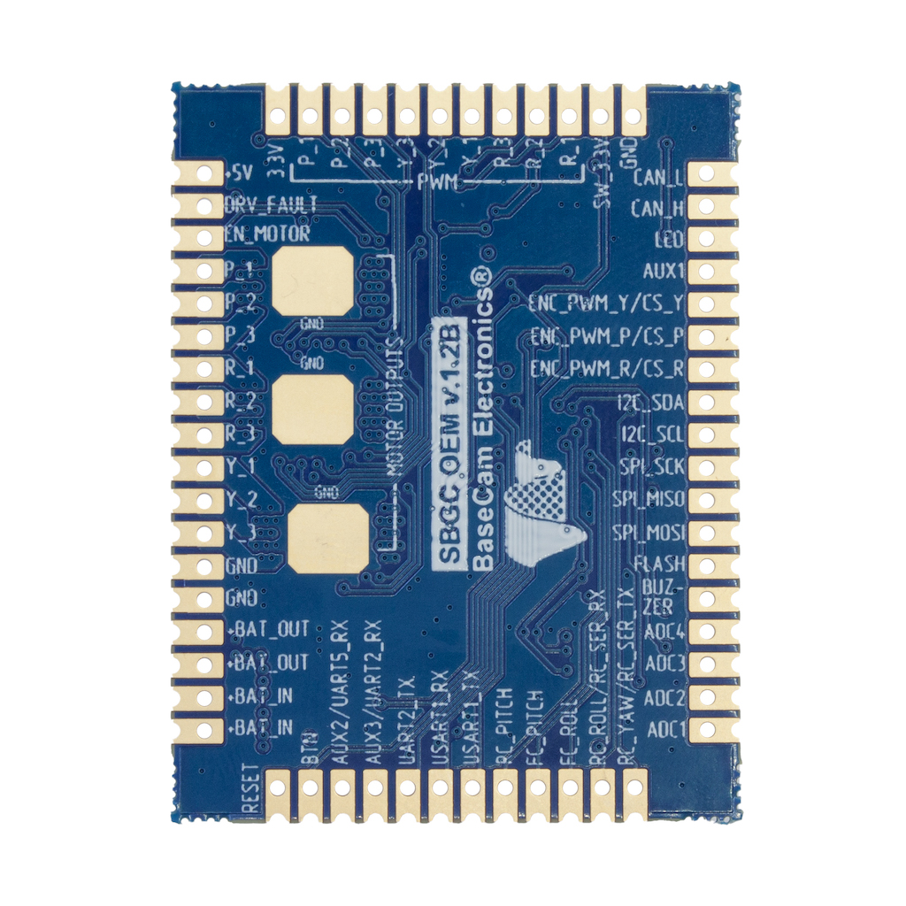
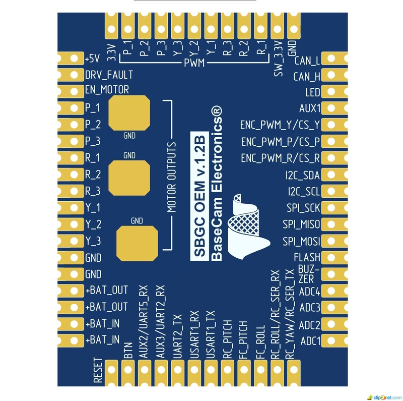
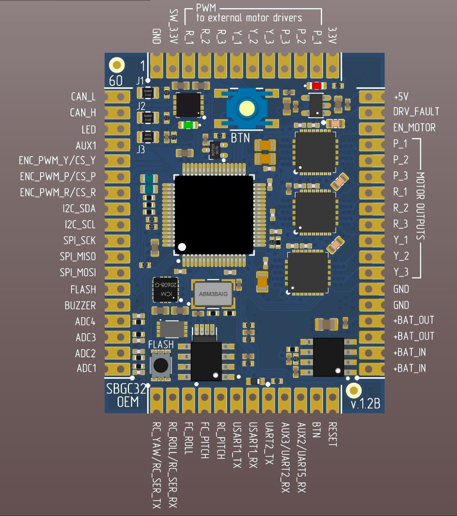
Built-in IMU sensor, can be used as a second frame sensor or as the main sensor.- Full set of interfaces that are common for our top-level controllers: SPI/PWM, I2C, CAN, 3x UART, 7x SDIO, 3x ADC
- Compact size and low profile
- 64-pin MCU with 256k FLASH and CAN bus support implements all the hardware and software functionality available in the "Extended" series of SBGC32 controllers while reducing the overall board size**
- The on-board current sensor can measure a power consumption of OEM controller as well as host controller, due to the power supply pass-through routing option.
- Components that are missed (to be located on the host controller): all connectors, 5V DC/DC regulator, USB-to-UART adapter for PC connection
* For maximum current capabilities good thermal dissipation should be provided;
** Supported functions depends on the license type. See Version comparison chart
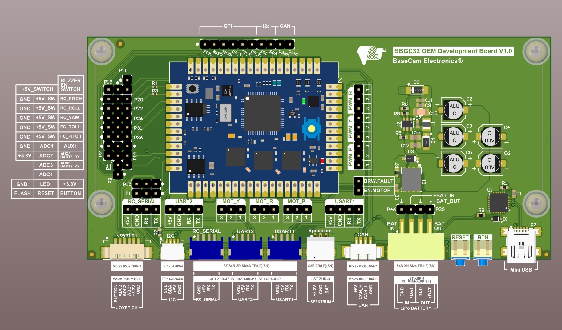
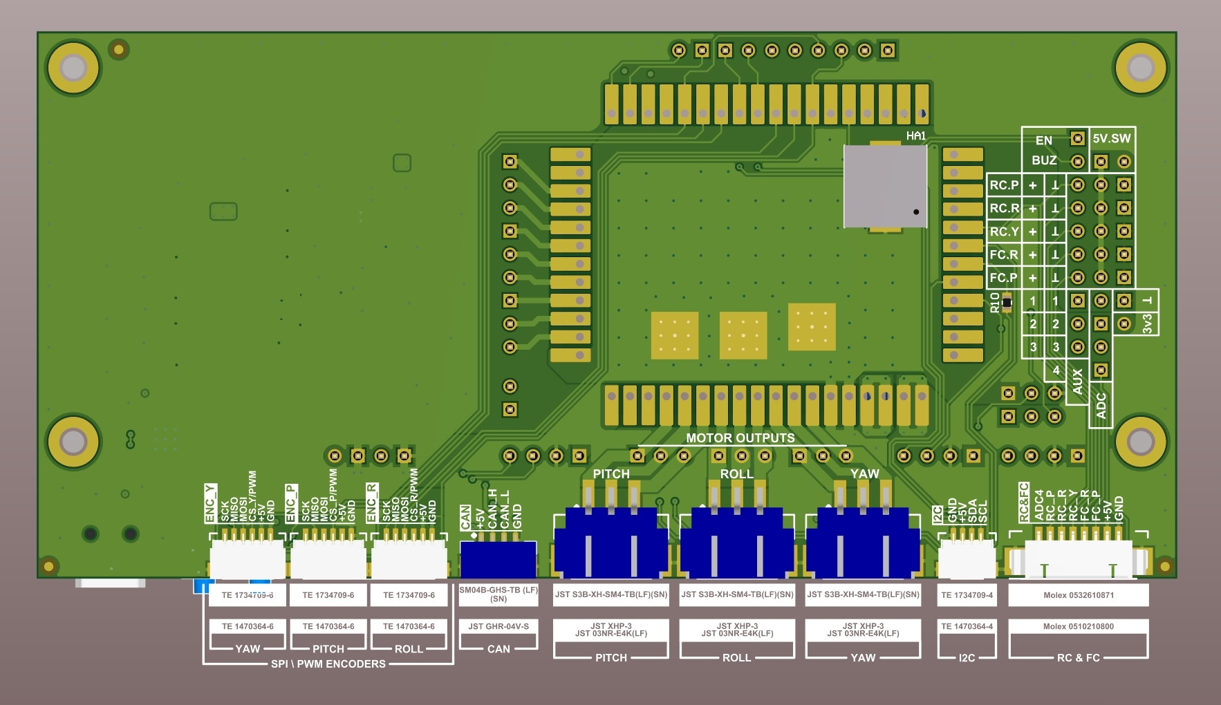
To evaluate OEM controller, the "OEM Development board" is available. It exposes all ports to handy connectors, has 5V DC/DC regulator, USB-to-UART converter, buttons and power line filtering capacitors - all that is needed to use OEM board as any other Basecam controller.
Specifications
| Size of the board: | 35×45x7 mm |
| Power supply voltage: | 5–26 V (2s - 6s LiPo) |
| Maximum motor current: | 5A peak, ~1.5A continuous per motor* |
| +5V supply requirements: | 4.0V x 200mA min, 5.0V x 500mA recommended** |
* Board dissipates heat through a dedicated PCB layer and soldering pads on the bottom, directly connected to the drivers, allowing an external heat-sink on the host controller to be used;
** If CAN bus is used, pay special attention to +5V voltage stability in board and connected modules, avoiding excessive voltage drop on cables or connectors
Downloads
SBGC32 OEM controller
General Connection Diagram for Boards ver.3.0 (97Kb 16.05.2014) 3D CAD files (STEP) (1Mb 28.03.2022) Schematics & footprint (Altium) (4Mb 13.06.2023)SBGC32 OEM Development board
Development board manual (including schematics and footprint) (2Mb 12.04.2024) More downloads…Support
Type your question or comment below. Answer will be sent at your E-mail within 24 hours on workdays.
WARNING: The motor drivers used in this controller are more compact and efficient but produce more EM interference compared to "Regular" and "Extended" boards; special actions are required to prevent interference on digital signal lines (I2C or PWM) and nearby electronics:
- Installing filters on the power supply cable (several turns on a ferrite ring); limiting its length to 70 cm;
- Installing filters on motor outputs and/or shielding the cable:
- LRC-filter (see schematics)
- Ferrite ring on the cable
- Installing filters on the digital signal lines (several turns on a ferrite ring); using twisted pairs for I2C (SDA+VCC, SCL+GND) and/or shielding them;